The Essential Guide to Precision Sheet Metal Prototyping Success

What Is Precision Sheet Metal Prototyping — and Why It Matters
Precision sheet metal prototyping is the process of creating accurate, functional metal parts from flat sheet stock — using techniques like laser cutting, CNC bending, and welding — before committing to full-scale production.
Here is a quick overview:
| Question | Answer |
|---|---|
| What is it? | Creating test parts from sheet metal to validate design, fit, and function |
| Common materials | Aluminum, stainless steel, copper, cold rolled steel |
| Key processes | Laser cutting, press brake forming, welding, hardware insertion |
| Typical lead times | As fast as 1–15 business days depending on complexity |
| Who uses it? | Automotive, aerospace, electronics, medical, and defense industries |
| Main benefit | Catch design problems early — before expensive production tooling is made |
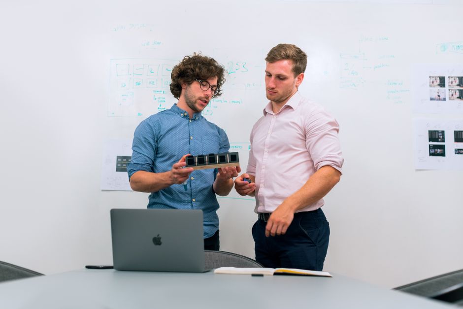
When a product design moves from a digital file to a real, physical metal part, a lot can change. Holes may land in the wrong place. Bends may cause unexpected stress. Tolerances that looked fine on screen may not hold up under real-world conditions. Precision sheet metal prototyping solves this by giving engineers a production-representative part to test, measure, and refine — without the high cost and long lead times of full production tooling.
This is especially critical in industries like automotive manufacturing, where a single design flaw caught at the prototype stage can save weeks of delays and significant rework costs on the production floor.
I'm Yoshihiro Hidaka, founder of Hidaka USA, Inc., and I have been delivering precision sheet metal prototyping to the automotive industry since 1989 — first as a prototype supplier, and later expanding into mass production as well. In the sections that follow, I'll walk you through everything you need to know to succeed with sheet metal prototyping, from design best practices to transitioning smoothly into high-volume production.

Terms related to precision sheet metal prototyping:
- High precision stamping services
- Precision railcar stamping
- precision metal stamping manufacturer Ohio
Understanding the Precision Sheet Metal Prototyping Process
At its core, precision sheet metal prototyping is both an art and a science. Unlike production fabrication, which focuses on speed and cost-per-unit through "hard tooling" (like expensive steel dies), prototyping relies on "soft tooling" and flexible CNC machinery. This allows us to make changes on the fly without breaking the bank.

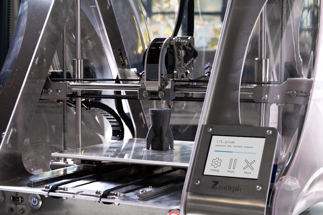
The journey begins with a 3D CAD model. In modern manufacturing, we don’t just "wing it." We use digital validation to ensure that the flat pattern of the metal will actually fold into the shape you’ve designed. This stage often involves an automated Design for Manufacturability (DFM) review, where software and experienced engineers check for "non-manifold" edges or surface gaps that could cause hiccups during fabrication.
Automation plays a massive role today. From AI-powered quoting systems that analyze your geometry in minutes to CNC-controlled press brakes that remember exactly how much pressure to apply to a specific alloy, technology has squeezed lead times from weeks down to just a few days.
| Feature | Prototyping (Soft Tooling) | Production (Hard Tooling) |
|---|---|---|
| Primary Goal | Design validation & speed | Low unit cost & consistency |
| Setup Cost | Low | High (Due to custom dies) |
| Flexibility | High (Easy to change design) | Low (Hard to change design) |
| Cutting Method | Laser or Waterjet | Stamping or Blanking |
Key Steps in Precision Sheet Metal Prototyping
To get from a digital idea to a physical part, we follow a disciplined workflow:
- Design Review & DFM: We analyze the CAD file to ensure holes aren't too close to bends and the material is thick enough for the intended use.
- Material Nesting: To reduce waste and our carbon footprint, we use software to "nest" as many parts as possible onto a single metal sheet.
- CNC Programming: The laser cutter and press brake receive digital instructions directly from the CAD data, ensuring high fidelity to your original vision.
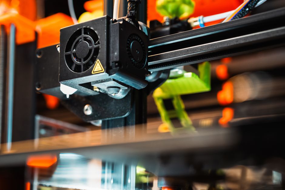
- Laser Cutting: A high-powered fiber laser slices through the sheet with incredible precision (often within ±0.1 mm).
- Bending Sequence: A technician uses a CNC press brake to fold the metal. The order of the bends matters—if you do them in the wrong order, the part might collide with the machine!
- Hardware & Assembly: This includes hardware insertion (like PEM® nuts), welding, and any required secondary operations.
- Final Inspection: Every part is checked against the original prints to ensure it meets the required specs.
Quality Control and Tolerances in Precision Sheet Metal Prototyping
In precision sheet metal prototyping, "close enough" isn't good enough. We generally adhere to ISO 2768 standards for general tolerances, but for critical features, we can achieve much tighter accuracy.
Standard linear tolerances often sit around ±0.005 inches, while angular tolerances for bends are typically within ±1 degree. To verify this, we use First-Article Inspection (FAI) and Coordinate Measuring Machines (CMM). These tools allow us to probe the physical part and compare it to the digital "master" to ensure every hole and flange is exactly where it belongs.
If you are looking to initiate a project, understanding these standards early helps prevent "tolerance stack-up" issues when you eventually assemble multiple parts together.
Material Selection and Advanced Fabrication Techniques
Choosing the right material is the most important decision you'll make after the design itself. Each metal has a "personality"—some love to be bent, others are brittle, and some conduct heat like a champ.
Common Materials and Their Properties
- Aluminum (e.g., 5052-H32, 6061-T6): The superstar of prototyping. It’s lightweight, corrosion-resistant, and easy to form. 5052 is the go-to for parts requiring complex bends, while 6061 is stronger but can be prone to cracking if the bend radius is too tight.
- Stainless Steel (304/316): Known for its strength and rust resistance. It’s a bit tougher on tools but essential for medical devices or outdoor applications.
- Cold Rolled Steel (CRS): An affordable, versatile option that’s great for internal brackets and structural components. It usually requires a finish (like powder coating) to prevent rust.
- Copper & Brass: These are chosen for their electrical conductivity and thermal management. They are softer and require specialized laser settings because they are "reflective" metals.
Fabrication Techniques
We use a variety of high-tech methods to shape these materials:
- Laser Cutting: The fastest way to get a 2D profile. It’s incredibly precise but can leave a small "heat-affected zone" on the edge.
- Waterjet Cutting: Uses high-pressure water mixed with abrasive garnet. It’s slower than a laser but produces no heat, which is perfect for thick materials or metals that are sensitive to temperature.
- Press Brake Forming: This is where the 2D flat becomes a 3D part. Modern brakes use CNC controllers and sometimes magnetic braking to provide uniform clamping force for perfect bends.
- Welding (TIG/MIG): For complex assemblies, we join parts using precision welding. In industries like automotive, the strength of these joints is paramount.
Finishing Options
A prototype isn't just about shape; it's about "fit and finish." Common options include:
- Powder Coating: Provides a durable, colorful, and protective "skin."
- Anodizing: Primarily for aluminum, it increases corrosion resistance and can add color.
- Plating (Zinc, Nickel, Gold): Used for conductivity or extreme rust protection.
- Passivation: A chemical treatment for stainless steel to enhance its natural corrosion resistance.
- Deburring/Tumbling: Essential for removing sharp edges and "burrs" left over from the cutting process.
Design for Manufacturability (DFM) and Best Practices
The secret to a successful prototype is designing it with the machine in mind. This is called Design for Manufacturability, or DFM. If you ignore DFM, you'll end up with a part that looks great on your screen but is impossible (or very expensive) to build.
Pro-Tips for Sheet Metal Design:
- The 1X Bend Radius Rule: Generally, your inside bend radius should be at least equal to the material thickness. If the metal is 0.060" thick, try to use a 0.060" radius. This prevents the metal from cracking or "necking."
- Hole Placement: Keep holes at least 2X the material thickness away from any bend. If a hole is too close, it will stretch into an oval shape when the metal is folded.
- Bend Reliefs: When a bend doesn't go across the entire width of a part, you need a "relief notch." Think of it as a tiny cut that lets the metal fold without tearing the adjacent material.
- Uniform Thickness: Sheet metal parts must maintain a uniform wall thickness. You can't have a part that is 0.125" thick in one spot and 0.060" thick in another—unless you're willing to pay for expensive CNC machining.
- Simplify for Speed: If you can customize a template or use standard hole sizes, you'll reduce the need for custom tooling and speed up your delivery.
Transitioning from Prototype to Mass Production
Once your prototype is validated, it's time to think about the "big show": mass production. This transition is where many projects stumble, but a little planning goes a long way.
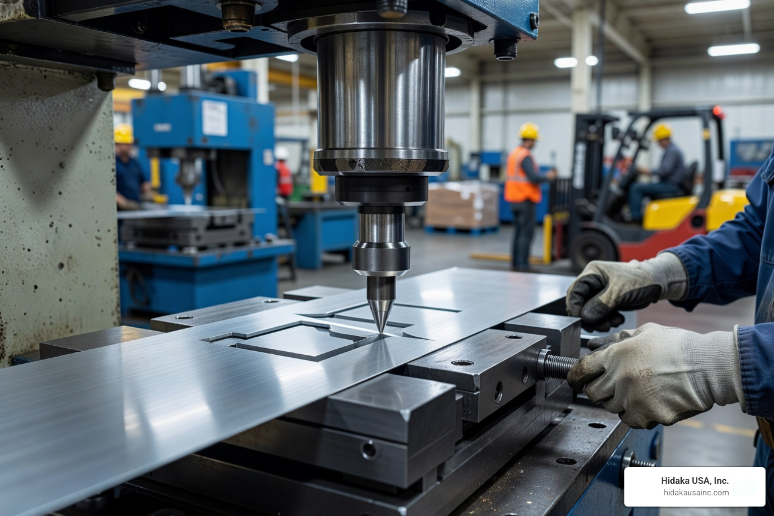
The biggest shift is moving from Soft Tooling to Hard Tooling. While laser cutting is great for 50 parts, it’s too slow for 50,000. For high volumes, we use custom-engineered stamping dies. These dies are a significant upfront investment, but they drop the cost-per-part to a fraction of the prototype price.
Strategies for a Smooth Scale-Up:
- Design Simplification: Can two parts be combined into one? Can you use a thinner gauge of metal without losing strength? Small changes can save thousands of dollars in a production run.
- Repeatability: Ensure your prototype design doesn't rely on "hand-tweaking." It must be something a machine can reproduce identically every time.
- Supply Chain Integration: At Hidaka USA, Inc., we help our clients manage the transition by offering mass production services in-house. This means the same engineers who helped with your prototype are overseeing the production tooling.
- Lead Time Management: Production tooling can take weeks or months to build. We often recommend a "bridge" run—using prototyping methods to keep your assembly line moving while the hard tools are being finished.
Frequently Asked Questions about Precision Sheet Metal Prototyping
How do lead times compare between prototyping and production?
Prototyping is built for speed. Depending on the complexity, you can often get a quote in minutes and have parts in hand in 1 to 15 business days. Mass production, however, involves building custom dies and setting up assembly lines, which can take anywhere from 4 to 12 weeks or more for the initial setup.
What are the key advantages of precision sheet metal prototyping?
The biggest advantage is risk mitigation. It allows you to perform functional testing and real-world simulation without the $50,000+ price tag of a production die. It also offers incredible design flexibility; if a part doesn't fit, we just update the CAD file and cut a new one the next day. Compared to 3D printing, sheet metal prototypes provide the actual strength, conductivity, and heat resistance of the final product.
Which industries benefit most from precision metal prototypes?
- Automotive: For brackets, chassis components, and heat shields.
- Aerospace: For lightweight enclosures and avionic housings.
- Electronics: For EMI/RFI shielding and server rack components.
- Medical: For surgical instrument trays and equipment frames.
- Renewable Energy: For busbars and battery enclosures.
Conclusion
Mastering precision sheet metal prototyping is the most effective way to accelerate your product development cycle. By catching errors early and validating your design with production-representative materials, you ensure that your final product is high-quality, functional, and cost-effective.
At Hidaka USA, Inc., we have spent over three decades perfecting this process. From our 95,000-square-foot facility in Dublin, Ohio, we provide the American-made quality that the automotive and motorsports industries depend on. Whether you need a single bracket or are ready to scale to thousands of assemblies, our ISO 9001-certified team is here to guide you from the first laser cut to the final production run.
Ready to see your design come to life? Contact Hidaka USA, Inc. to discuss your project and experience the precision that only decades of expertise can provide.