A Step-by-Step Guide on How to Prototype Metal Parts

Why Metal Prototyping Is a Critical Step in Product Development
How to prototype metal parts is a process that follows these core steps:
- Define your goals - Set design requirements, tolerances, and testing criteria
- Create a 3D CAD model - Use software like SolidWorks to design your part
- Choose a prototyping method - CNC machining, 3D printing, casting, or sheet metal fabrication
- Select your material - Aluminum, stainless steel, titanium, or other metals based on your application
- Fabricate the prototype - Manufacture the part using your chosen method
- Apply surface finishing - Anodizing, powder coating, or other treatments
- Test and validate - Run durability, fatigue, and fit tests, then refine as needed
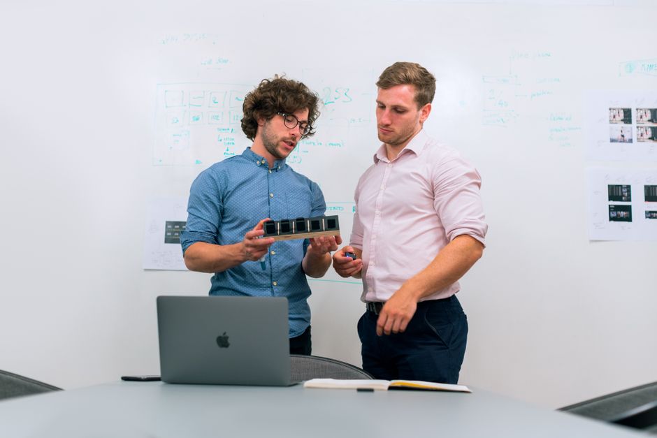
Before a metal part ever reaches an assembly line, it needs to be tested, validated, and refined. That process is called metal prototyping - and it is one of the most important stages in product development. A physical metal prototype lets engineers catch design flaws early, verify that components fit together correctly, and confirm that the part performs as expected under real conditions.
This matters more than most people realize. Studies show that roughly 30% of designs require changes after the first prototype is built. Catching those issues before committing to full production tooling saves significant time, cost, and risk - especially in high-stakes industries like automotive manufacturing.
Each prototyping method - whether CNC machining, additive manufacturing, casting, or sheet metal fabrication - has its own strengths, lead times, and ideal use cases. Choosing the wrong one can mean wasted iterations, inaccurate test results, or a prototype that does not reflect how the final part will actually behave in production.
My name is Yoshihiro Hidaka, and since founding Hidaka USA, Inc. in 1989 as a sheet metal fabrication company supplying prototypes to the automotive industry, I have spent over three decades helping manufacturers understand how to prototype metal parts efficiently and accurately. In this guide, I will walk you through every stage of the process - from method selection and material choice to testing and transitioning to mass production.

Know your how to prototype metal parts terms:
Core Methods for How to Prototype Metal Parts
When we look at the landscape of manufacturing, there isn't a "one size fits all" solution for creating a metal prototype. The method we choose depends on what the part needs to do, how many we need, and how quickly we need them.
In our facility in Dublin, Ohio, we often see projects that require a mix of these technologies. Here is a quick comparison of the heavy hitters in metal prototyping:
| Feature | CNC Machining | 3D Printing (DMLS) | Investment Casting | Sheet Metal Fabrication |
|---|---|---|---|---|
| Primary Strength | Precision & Strength | Complex Geometry | Mass Production Intent | Speed & Durability |
| Tolerance | ±0.01 mm | ±0.1 mm to ±0.2 mm | Moderate | Varies by thickness |
| Best For | Functional testing | Lightweighting/Lattices | Complex engine parts | Brackets, Enclosures |
| Lead Time | Fast (Days) | Fast (Days) | Slow (14-21 Days) | Very Fast (Days) |
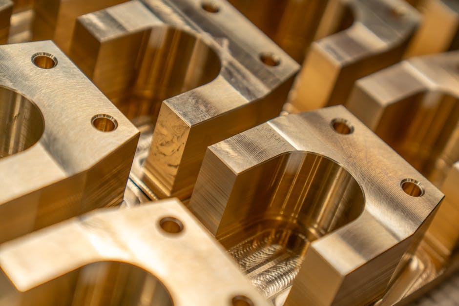
Precision CNC Machining: How to Prototype Metal Parts with Tight Tolerances
If you need a part that is identical in strength and precision to a final production piece, CNC (Computer Numerical Control) machining is often the go-to. It is a subtractive process, meaning a machine starts with a solid block of metal and carves away material using high-speed rotating tools.
The biggest advantage here is accuracy. We can achieve tight tolerance levels up to ±0.01 mm. This makes it the "honorable mention" for any part that requires a perfect fit within an assembly. Since it uses solid billets of production-grade metal, the mechanical properties of the prototype are exactly what you would expect in the final product.
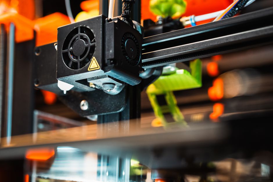
3D Printing and Additive Manufacturing
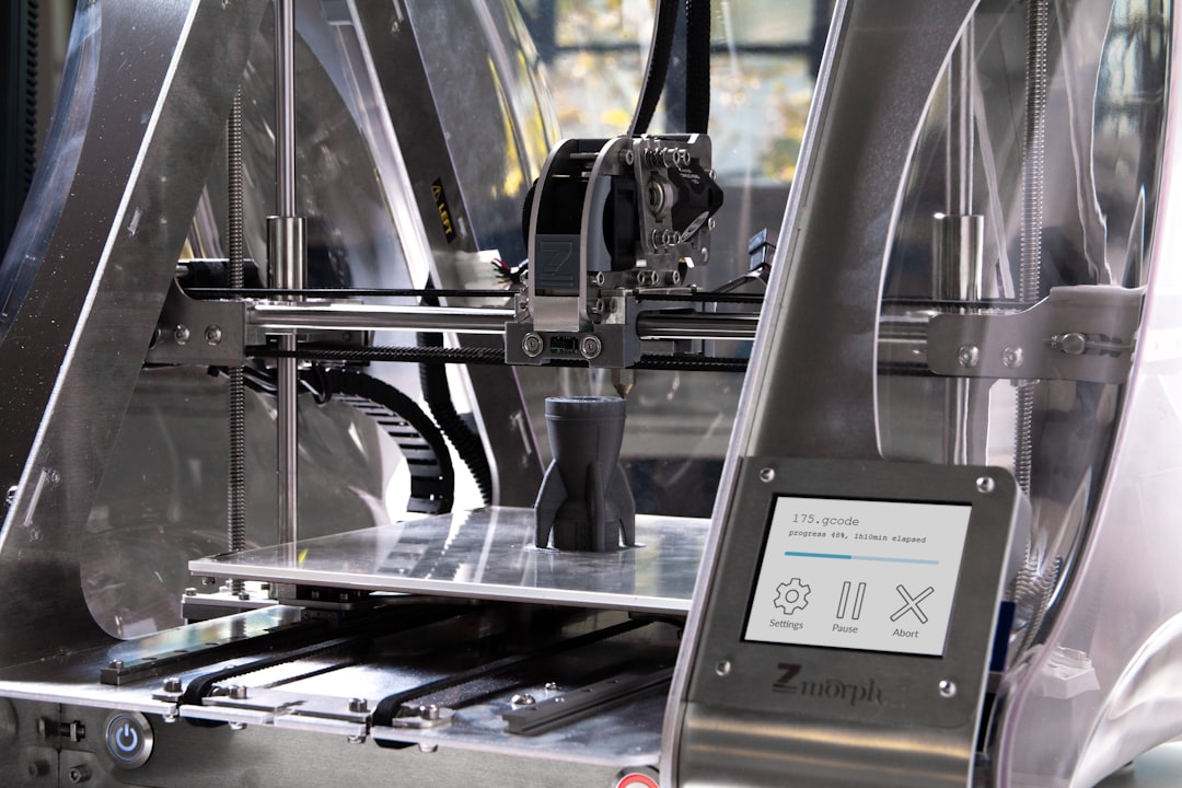
On the flip side of subtractive manufacturing is additive manufacturing, or 3D printing. Processes like Direct Metal Laser Sintering (DMLS) or Binder Jetting build parts layer by layer from metal powder. If you want a general overview of how additive manufacturing works, the Wikipedia article on 3D printing is a helpful reference.
This technology has revolutionized the industry by allowing us to create "impossible" geometries-like internal cooling channels or lattice structures that reduce weight without sacrificing strength. It is also a fantastic way to speed up the rapid prototyping phase. For example, some firms use 3D printed patterns to skip the expensive tooling phase of casting, allowing them to produce a metal part in just 5 days instead of weeks.
3D printing is also being used to create custom jigs and fixtures alongside prototypes to improve manufacturing efficiency.
Sheet Metal Fabrication and Forming
For many of our clients in the automotive and railcar industries, the final part will be made from thin sheets of steel or aluminum. In these cases, sheet metal prototyping is the most logical choice. We use 2D and 3D laser cutting to create the flat profile, then utilize hydraulic pressing and bending to form the final shape.
This method is incredibly cost-effective for low-volume runs and provides high durability. Because we use the same materials intended for mass production, the functional testing-like vibration or impact resistance-is highly accurate.
Selecting the Right Material and Technology
Choosing the right metal is just as important as choosing the right machine. We always tell our clients to look at the "big three" requirements: strength, weight, and environment.
- Aluminum 6061: The "workhorse." It is lightweight, easy to machine, and cost-effective.
- Stainless Steel 316: Essential for marine or medical applications where corrosion resistance is paramount.
- Titanium: Used in aerospace and high-end motorsports (like the ones we serve in Ohio) for its incredible strength-to-weight ratio.
- Copper and Brass: Chosen for electrical conductivity or aesthetic appeal.
When designing, you can explore various materials to see how different composites or metal-filled filaments might behave during the early conceptual stages.
Matching Prototype Methods to Mass Production
One of the most common mistakes we see is a "prototype-production mismatch." If you prototype a part using 3D printing but plan to mass-produce it via casting, your test results might be misleading.
We always recommend aligning your prototyping method with your transitioning to mass production plan. This ensures that the tolerances, surface finishes, and structural integrity remain consistent when you scale from one unit to ten thousand.
Step-by-Step Process for Successful Metal Prototyping
Step 1: Define Goals
What is this prototype for? Is it a "looks-like" model for an investor meeting, or a "works-like" model that needs to survive 500 hours of stress testing? Defining this early prevents over-engineering and keeps costs down.
Step 2: 3D CAD Modeling
Everything starts in the digital world. Using CAD (Computer-Aided Design) software, we create a 3D representation of the part. This is where we perform initial Finite Element Analysis (FEA) to predict where the part might fail.
Step 3: Method Selection
Based on your goals and the complexity of the CAD model, we select the method. If it’s a complex bracket, we might go with sheet metal. If it’s a high-precision valve, CNC machining is the winner.
Step 4: Fabrication
This is where the magic happens. The machines take over, guided by the G-code generated from the CAD file. Whether it's the laser cutter sparking through steel or the CNC mill carving aluminum, the physical part begins to take shape.
Step 5: Finishing
Raw metal parts often need a little "polish." Surface finishing can include:
- Anodizing: For corrosion resistance and color.
- Powder Coating: For a durable, thick protective layer.
- Bead Blasting: To create a uniform, matte texture.
Design Considerations for How to Prototype Metal Parts
Design for Manufacturability (DFM) is the secret sauce of successful prototyping. Here are a few rules we live by:
- Bend Radii: In sheet metal, if you try to bend a part too sharply, the metal will crack. We typically use standard radii like 0.030 in. or 0.060 in.
- Hole Placement: Keep holes at least 4x the material thickness away from any bend lines to prevent deformation.
- Tool Access: It sounds simple, but you’d be surprised how many designs have a screw located where a screwdriver can't actually reach!
- Springback: Metals like to "spring back" slightly after being bent. We have to over-bend the part in the design phase to account for this.
Testing and Validating Your Metal Prototype
Once the part is in your hands, the real work begins. We don't just "hope" it works; we prove it.
We use several validation processes:
- Mechanical Testing: Using a Universal Testing Machine (UTM) to pull, push, and twist the part until we know its breaking point.
- NDT (Non-Destructive Testing): Using ultrasonic or X-ray testing to look for internal cracks without destroying the prototype.
- Thermal Cycling: Heating and cooling the part repeatedly to see how it handles expansion and contraction.
- Fatigue Testing: Simulating years of use in a matter of days.
For those using advanced additive methods, technical support and validation resources are essential to help interpret test data. At Hidaka USA, Inc., we maintain ISO 9001 standards to ensure every test is documented and every part meets the rigorous requirements of the automotive and rail industries.
Frequently Asked Questions about Metal Prototyping
How much does it cost to prototype metal parts?
The cost varies based on the method. For example, adjusting a hard tool for a design change in traditional casting can cost roughly $650 per adjustment. In contrast, 3D printing a new design for a casting pattern might only cost around $15 per part. CNC machining is generally more expensive per unit due to material waste and machine time, but it saves money by eliminating the need for expensive molds or dies.
How long does the metal prototyping process take?
Speed is the name of the game. A standard CNC or sheet metal prototype can often be turned around in 5 days. However, more traditional methods like investment casting can take 14 to 21 working days because the molds need time to be prepared and the metal needs time to solidify properly.
Can I transition directly from a prototype to mass production?
Yes, provided you used "production-intent" materials and methods. If we fabricate a bracket using our high-tonnage hydraulic presses during the prototyping phase, the transition to mass production is seamless because the manufacturing "DNA" is already there.
Conclusion
At Hidaka USA, Inc., we believe that a prototype is more than just a sample; it is a promise of what the final product will be. Whether we are working on a specialized component for a motorsports team or a structural assembly for a mass-transit railcar, our focus is always on precision, quality, and American-made reliability.
From our 95,000-square-foot facility in Dublin, Ohio, we combine decades of engineering expertise with advanced technology like 3D laser cutting and AWS-certified welding. We understand the high stakes of the industries we serve, and we are here to help you navigate the complexities of how to prototype metal parts.
Ready to bring your design to life? We would love to have a conversation about your specific requirements and how our engineering team can support your goals. Hidaka USA, Inc. remains your primary contact for end-to-end prototyping and production.
Let’s build something that lasts. Contact us today to start your next metal prototyping project.