Putting the Pieces Together: Custom Laser Prototype Assemblies

From CAD File to Complete Assembly: What You Need to Know
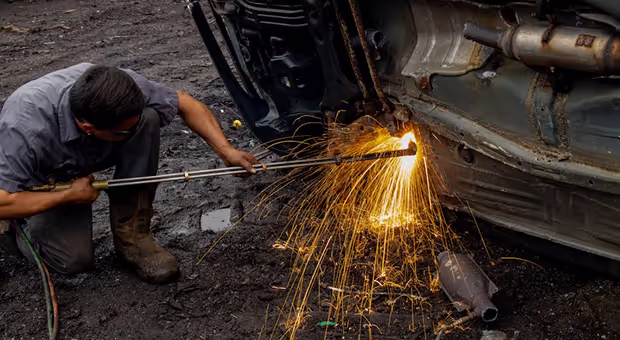
Laser cut prototype assemblies are multi-part systems made by cutting flat metal shapes with a focused laser beam, then joining those parts into a functional structure through bending, welding, or hardware insertion.
Quick answer — how laser cut prototype assemblies work:
- Design — Engineer creates a CAD file with all flat part profiles
- Cutting — A CNC laser cuts each part from sheet metal to tight tolerances (typically ±0.005 in. or better)
- Forming — Parts are bent or formed on a press brake as needed
- Joining — Parts are assembled using welding, riveting, or hardware insertion
- Finishing — Assembly is deburred, coated, or surface-treated for production-ready quality
For automotive engineers and product developers, the appeal is straightforward. A bracket, housing, or structural frame can go from a digital drawing to a testable physical assembly in days — not weeks. There is no need to invest in hard tooling, and design changes can be made between iterations without scrapping expensive dies.
This speed matters when your assembly line depends on accurate, functional prototypes to validate a design before committing to mass production. A single tolerance error or misaligned feature caught at the prototype stage saves significant time and cost downstream.
I'm Yoshihiro Hidaka, founder of Hidaka USA, Inc., where I've spent over three decades supplying laser cut prototype assemblies to the automotive industry and beyond, starting from our sheet metal fabrication facility in Dublin, Ohio. That hands-on experience is the foundation of everything covered in this guide.

Key laser cut prototype assemblies vocabulary:
Understanding Laser Cut Prototype Assemblies
When we talk about laser cut prototype assemblies, we are moving beyond simple flat parts. While a single laser-cut bracket is useful, an assembly represents a multi-part system—think of an automotive seat frame, an avionics housing, or a complex electronic enclosure. These systems require multiple 2D flat patterns to be cut with extreme precision so they can fit together perfectly in three-dimensional space.
At our facility in Dublin, Ohio, we utilize high-powered CNC lasers to transform raw sheet stock into these intricate components. The beauty of this process is the "CAD-to-part" revolution. Because the laser follows a digital path, we can achieve a precision fit that traditional mechanical cutting simply cannot match. This is critical for managing "tolerance stack-up," which is the cumulative effect of small errors across multiple parts in an assembly.

One of the most significant advantages for our partners in the automotive and railcar industries is the elimination of tooling investment. Traditional stamping requires expensive "hard tooling" or blanking dies that can take weeks to manufacture. With laser-cut assemblies, we skip the die-making phase entirely. This allows for unmatched design flexibility; if a mounting hole needs to move by 2mm after the first test, we simply update the CAD file and cut a new version the next day.
Key Advantages of Laser Prototyping
Why do engineers choose laser cutting for their assemblies? It boils down to a few high-impact benefits:
- Unmatched Speed: We can often deliver complex prototypes in as fast as 24 to 48 hours for rush orders. Standard lead times for quantities under 50 are typically around 3 to 5 business days.
- Extreme Accuracy: Laser cutting achieves tolerances of ±0.004” to ±0.005” (0.1 mm) with high repeatability. For specific high-performance applications, we can even push tolerances to ±0.001”.
- Complex Geometries: Lasers can cut intricate shapes, tiny holes, and complex contours that would be impossible or prohibitively expensive for a CNC mill or a mechanical punch.
- Superior Edge Quality: The high-heat beam vaporizes material, leaving behind smooth, narrow incisions. Often, the parts require little to no secondary edge finishing before assembly.
- Scalability: Once the prototype assembly is validated, the same CNC programs can be used to scale up to low or medium-volume production without significant re-engineering.
Common Materials for Laser Cut Prototype Assemblies
The versatility of laser cutting allows us to work with a wide range of alloys and materials. Selecting the right material is the first step in ensuring your assembly performs under real-world stress.
- Stainless Steel: Excellent for corrosion resistance and strength. We often use 304 and 316 grades for medical components and food-grade enclosures.
- Aluminum (6061-T6, 5052-H32): Lightweight and highly conductive. It is a staple in the aerospace and automotive sectors for brackets and housings.
- Carbon Steel (CRS/HRPO): The workhorse of the industry. It provides great structural integrity for heavy equipment and vehicle frames.
- Copper and Brass: These reflective metals are more challenging to cut, but our fiber lasers handle them with ease. They are essential for busbars, battery tabs, and electronic shielding.
- Specialty Alloys: We also process materials like Titanium and Nitinol for high-tech medical and military applications.
Technical Design and Tolerance Guidelines
Designing for laser cut prototype assemblies requires an understanding of how the laser interacts with the metal. Unlike a physical blade, a laser beam has a specific "width" called the kerf.
Optimizing CAD Files for Laser Cut Prototype Assemblies
To ensure your project moves through our Ohio facility smoothly, your CAD files should be prepared with the following best practices:
- File Formats: We prefer 3D STEP files or SOLIDWORKS (.sldasm) files for assemblies. For flat patterns, DXF or DWG files are standard.
- Closed Vector Paths: Ensure all cut lines are closed loops. A gap in the line means the laser won't finish the cut, leaving the part stuck in the sheet.
- Layer Management: Use different colors or layers to distinguish between "cut" lines and "etch" or "engrave" lines (used for part numbering or alignment marks).
- Tab-and-Slot Joints: One of our favorite techniques for assemblies is the tab-and-slot design. By including tabs on one part and corresponding slots on another, the assembly becomes "self-fixturing," meaning the parts align themselves perfectly for welding.
- Bend Reliefs: When a part needs to be bent after cutting, include small cutouts at the corners of the bend. This prevents the metal from tearing or deforming during the forming process.
Managing Kerf and Material Thickness
The "kerf" is the width of the material that the laser vaporizes. Typically, this is less than 0.2mm, but it varies based on material thickness and laser type. If you are designing a "press-fit" assembly where one part must slide snugly into another, you must account for this kerf in your design software.
At Hidaka USA, Inc., we operate high-wattage fiber and CO2 lasers capable of handling materials up to 3/4” (19mm) thick. However, for most prototype assemblies, we find the "sweet spot" for precision and speed is between 0.024” and 0.250”. As the material gets thicker, the laser may produce a slight "taper" on the edge due to beam divergence—something our engineers help you manage during the Design for Manufacturability (DFM) phase.
The Assembly Process: From Flat Parts to Functional Prototypes
Once the laser has done its job, the "flat" parts are only halfway to becoming a prototype. This is where our comprehensive manufacturing capabilities in Dublin, Ohio, truly shine. We don't just cut parts; we build systems.
Secondary Processes and Joining
Creating a functional assembly usually involves several secondary steps:
- Press-Brake Forming: We use hydraulic presses to create linear bends. This transforms flat sheets into 3D brackets, boxes, and chassis. Our bend angle tolerances are typically within ±1.0°.
- Hardware Insertion: We can install PEM nuts, studs, and standoffs. For a professional assembly, these fasteners are press-fitted into the laser-cut holes. Interestingly, adding hardware usually doesn't add to the lead time!
- Welding (MIG/TIG): For structural assemblies, we use AWS-certified welding. TIG welding is often preferred for prototypes because it provides a cleaner, more precise bead on thinner materials like aluminum and stainless steel.
- Riveting: In cases where welding might distract the material or where two different metals are being joined, we use mechanical riveting.
Best Practices for Joining Laser Cut Prototype Assemblies
To get the best results, we recommend "self-fixturing" designs. By using alignment tabs and slots, you reduce the need for expensive custom welding jigs. This keeps your costs down and speeds up the assembly process. Also, the minimum hole diameter should generally be equal to the material thickness to ensure a clean, vertical cut.
Secondary Finishing for Production-Ready Quality
A prototype shouldn't just work; it should look the part. We offer several finishing options:
- Deburring: Every part we cut is deburred to remove sharp edges and "dross" (hardened melt residue), making them safe to handle.
- Bead Blasting: This creates a uniform, matte finish and hides any small scratches from the manufacturing process.
- Powder Coating: For a production-ready look and extra durability, we can apply a variety of colors and textures.
- Passivation: Essential for stainless steel assemblies in medical or marine environments to prevent rust.
Comparing Laser Cutting to Alternative Prototyping Methods
How does laser cutting stack up against other popular prototyping methods?
| Feature | Laser Cutting | 3D Printing (Metal) | Waterjet Cutting | CNC Milling |
|---|---|---|---|---|
| Speed | Very High | Moderate | Moderate | Moderate |
| Tolerance | ±0.005" | ±0.010" | ±0.020" | ±0.001" |
| Material Range | High (Metals/Plastics) | Limited Alloys | Extremely High | High |
| Surface Finish | Excellent | Rough | Granular | Excellent |
| Cost (Small Batch) | Low | High | Moderate | High |
While 3D printing is great for complex internal cavities, it lacks the structural integrity and material variety of laser-cut metal. Waterjet cutting is excellent for very thick materials (over 1 inch) but is slower and less precise than a laser. For most sheet metal assemblies, laser cutting provides the best balance of speed, cost, and precision.
Frequently Asked Questions about Prototype Assemblies
What are the typical lead times for laser-cut assemblies?
At Hidaka USA, Inc., we pride ourselves on speed. Simple laser-cut parts can be ready in 1–3 days. For full laser cut prototype assemblies involving bending and welding, 5 business days is standard, though we offer expedited services for urgent automotive testing requirements.
How do I account for laser kerf in my assembly design?
Most modern CAD software allows you to set an "offset." However, for most prototypes, our CNC software handles kerf compensation automatically. If you are designing high-precision interlocking parts, we recommend a 30-minute design review with our engineers to dial in the exact offsets for your chosen material.
Can laser cutting handle thick materials for heavy-duty prototypes?
Yes! While laser cutting is optimized for sheets under 1/4", our high-powered 6,000-watt fiber lasers can cut through steel up to 3/4" thick. For assemblies requiring even thicker components, we can integrate laser-cut sheets with machined blocks or heavy-duty plates.
Conclusion
At Hidaka USA, Inc., we believe that a prototype is more than just a "test part"—it's a critical milestone in your product's journey. From our 95,000-square-foot facility in Dublin, Ohio, we combine over 30 years of experience with ISO 9001-certified quality standards to deliver laser cut prototype assemblies that meet the rigorous demands of the automotive and motorsports industries.
Whether you need a single functional prototype for a design review or a pilot run of 500 units, our team is ready to help you "put the pieces together" with American-made quality and precision.
Ready to see your design in 3D?Start your project with Hidaka USA, Inc.