A Smooth Operator's Guide to Hydraulic Prototype Forming

What Is a Hydraulic Prototype Forming Guide — and Why It Matters for Metal Fabrication
A hydraulic prototype forming guide covers the processes, tools, and best practices used to shape sheet metal parts using hydraulic pressure — before committing to full-scale production tooling. Here is a quick overview of the core process:
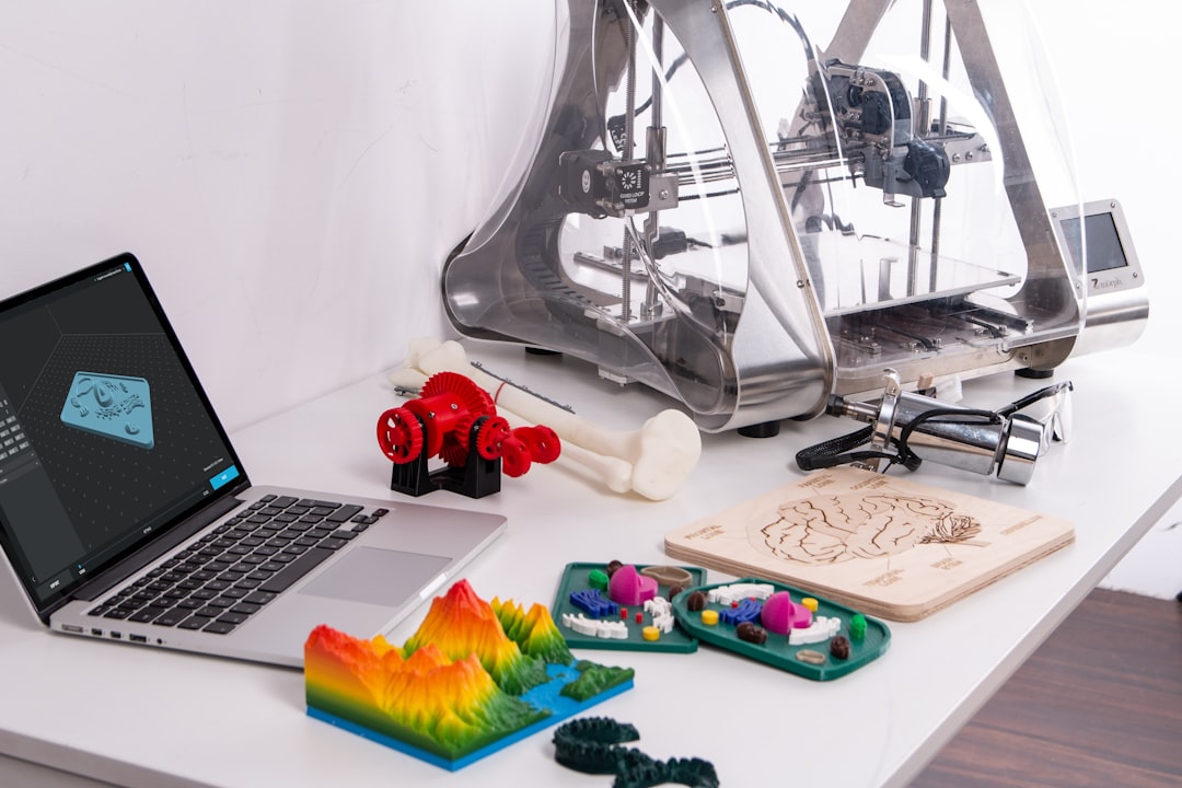
- Design the part and mold using CAD software (e.g., Fusion 360)
- Cut the sheet metal blank to size using waterjet or laser cutting
- Create tooling using 3D printed molds or traditional metal dies
- Form the metal by applying hydraulic pressure through a press or fluid bladder
- Inspect and iterate the formed part before moving to production
Hydraulic forming uses controlled fluid pressure — not impact force — to shape metal. This key difference allows for more complex geometries, better surface finishes, and less material waste compared to traditional mechanical stamping.
For automotive manufacturers, this matters. Tight deadlines and the need for accurate, repeatable parts mean that choosing the right forming method — and the right tooling — directly affects how fast a prototype moves to production.
Press-forming sheet metal is not a new idea. But today, advances in 3D printed tooling and hydraulic press technology have made it far more accessible, even for mid-sized manufacturers and prototyping labs working under real cost and time constraints.
My name is Yoshihiro Hidaka. Since founding Hidaka USA, Inc. in 1989 as a sheet metal fabrication company supplying prototypes to the automotive industry, I have spent decades refining every aspect of what a practical hydraulic prototype forming guide should include. The insights in this article draw directly from that hands-on experience in both prototype and mass production environments.
, compatible materials (aluminum, stainless steel, titanium), and tooling options (PLA, ABS-M30, PC, ULTEM 9085) labeled at each stage - hydraulic prototype forming guide infographic")
Understanding the Hydraulic Prototype Forming Guide: Process and Mechanics
To truly master this craft, we have to look under the hood. In traditional mechanical stamping, a heavy punch slams into a die to force the metal into shape. It’s fast, but it’s "violent" for the material. In contrast, hydraulic forming relies on plastic deformation achieved through steady, high-pressure fluid.
Whether we are using a flexible rubber bladder or direct fluid contact, the force is distributed evenly across the entire surface of the sheet. This results in parts with remarkably uniform thickness, even in deep-draw applications where mechanical stamping might cause the metal to thin out or tear.

When we talk about the hydraulic prototype forming guide, we usually categorize the mechanics into three main types:
- Hydroforming: Uses a pressurized fluid (often water or oil) to press the metal against a single-sided die.
- Rubber Pad Pressing: A flexible rubber block or diaphragm acts as one half of the die, conforming to the shape of a rigid mold on the other side.
- Fluid Cell Technology: A hybrid approach that uses a large bladder to apply massive, uniform pressure over an entire tray of parts.
FeatureHydroformingRubber Pad PressingTraditional StampingPressure MediumFluid/BladderFlexible RubberRigid Steel PunchTooling CostLow (Single Die)Very LowHigh (Matched Set)Surface FinishExcellentGoodFair (Tool Marks)ComplexityHighModerateModerateCycle TimeSlowerModerateVery Fast
For a deeper dive into these engineering principles, The Ultimate Guide for Engineers and Manufacturers provides an excellent technical foundation.
Key Materials for a Hydraulic Prototype Forming Guide
Not all metals play nice with hydraulic pressure. In our Dublin, Ohio facility, we typically work with materials known for their ductility and malleability.
- Aluminum (2024, 6061, 7075): The "bread and butter" of aerospace and automotive prototyping. It is lightweight and forms easily, especially in the "O" (annealed) temper.
- Stainless Steel (321, 347, 4130): Known for strength and heat resistance. These require higher pressures (often up to 10,000 psi) and may experience more work hardening.
- Titanium: A specialist material that offers an incredible strength-to-weight ratio but demands precise pressure control to avoid cracking.
A critical limitation to keep in mind for this hydraulic prototype forming guide is material thickness. Most hydraulic prototyping setups are optimized for sheets up to 0.090 inches (2.29 mm) or roughly 1/8 inch for softer aluminum. Beyond this, the tonnage required to move the metal increases exponentially. For a reference on standard thicknesses, you can consult this resource on Sheet Steel Gauges and Thicknesses.
Tooling Materials and Pressure Limits in the Hydraulic Prototype Forming Guide
One of the most exciting shifts we’ve seen is the move from expensive steel dies to 3D printed "soft" tooling. This allows us to fail fast and iterate even faster. However, you must match your 3D printing material to the forming pressure required:
- ABS-M30: Best for low-pressure applications under 3,000 psi. It’s affordable but has the shortest tool life.
- Polycarbonate (PC): A great middle-ground for pressures up to 6,000 psi.
- ULTEM 9085: The heavyweight champion. This FDM material can withstand up to 10,000 psi and is often used for high-strength stainless steel or titanium parts.
Because FDM prints are inherently porous, they actually have a hidden advantage: they don't require venting holes. Trapped air simply bleeds through the layers of the plastic tool! For more on these specifications, check out the Technical Application Guide for FDM Tooling.
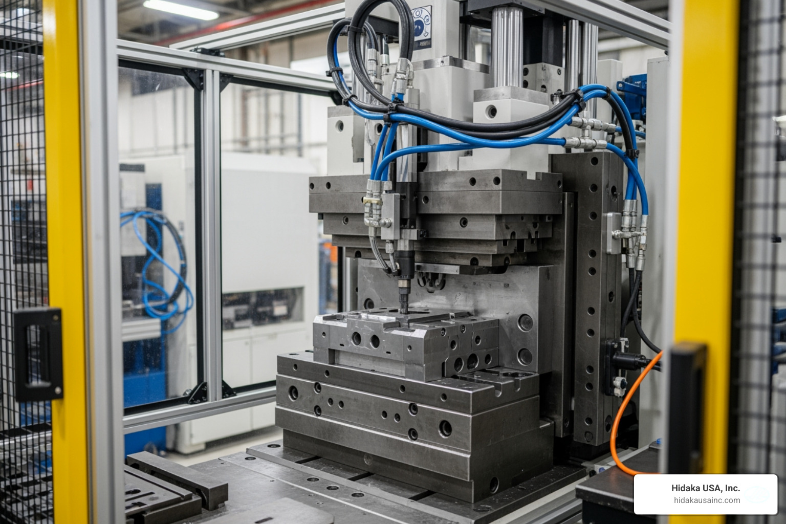
Core Technologies in Hydraulic Prototyping
At Hidaka USA, Inc., we look at hydraulic prototyping through two primary lenses: sheet and tube.
Sheet Hydroforming involves placing a flat blank over a male or female die. A bladder expands, forcing the metal to take the shape of the tool. This is perfect for car body panels, brackets, and enclosures.
Tube Hydroforming is slightly more "magical." We take a pre-bent tube, place it inside a female-female die set, and seal the ends. We then pump high-pressure fluid inside the tube, expanding it outward to meet the die walls. This creates incredibly strong, lightweight structures like engine cradles and bicycle frames.
Advantages of Hydraulic Methods Over Traditional Stamping
Why go through the trouble of hydraulic forming when stamping has worked for a century?
- Structural Integrity: Because the pressure is uniform, the material flow is more natural. This leads to fewer "thin spots" and better fatigue resistance.
- Reduced Welding: We can often form complex, multi-featured parts in one go that would otherwise require three or four separate stamped parts welded together.
- Minimal Springback: In some cases, the slight deflection of a plastic 3D printed tool actually helps "over-set" the metal, reducing the amount of springback we have to account for in the design.
- Lead Time: We can go from a CAD file to a physical metal part in 24 to 48 hours using 3D printed dies, compared to weeks for CNC-machined steel tooling.
Rapid Tooling: 3D Printing for Hydraulic Forming
If you want to save money (and who doesn't?), 3D printing is your best friend. We've seen tooling costs drop by as much as 85% when switching from outsourced metal dies to in-house printed versions.
To make a 3D printed tool survive the "squeeze," follow these best practices:
- Infill Density: Use at least 65% infill (we often go higher for high-pressure runs).
- Shell Count: Increase your wall thickness to 4 or 5 shells to ensure the edges don't collapse.
- Negative Air Gaps: In your slicing software, set air gaps to slightly negative values (e.g., -0.0005 in) to ensure the plastic is as dense as possible.
- Post-Processing: Sand the forming surfaces with 120 to 320 grit sandpaper. A smoother tool means a smoother part and less friction during the draw.
Design Considerations and Best Practices
Success in the hydraulic prototype forming guide isn't just about the press; it’s about the preparation.
- Lubrication: This is non-negotiable. We use water-based detergents or simple WD-40 to help the metal slide over the tool. Avoid petroleum-based lubes if you are using plastic tools, as they can degrade the mold.
- Alignment Guides: Use M3 screws or dowel pins to ensure your sheet metal blank doesn't shift when the pressure starts to build.
- Simulation: Before you press "start," use software like Fusion 360 or Autoform. These tools can predict where the metal might wrinkle or tear, saving you from wasting expensive material.
- Intensifiers: If you have a particularly sharp corner that isn't forming correctly, you can use a small plastic "intensifier" block to help push the metal into that specific area.
Frequently Asked Questions about Hydraulic Forming
What is the maximum material thickness for 3D printed hydraulic tools?
While industrial presses can handle thick plates, 3D printed "soft" tooling is generally limited to materials up to 0.090 inches (about 2.3 mm). Beyond this thickness, the pressure required to form the metal often exceeds the compressive strength of the plastic mold, leading to tool deformation or "mushrooming."
How many cycles can a plastic mold withstand in a hydraulic press?
You might be surprised! With proper design and materials like ULTEM 9085, we have seen plastic tools last for 400+ cycles. Usually, the tool "stabilizes" after the first 10 parts (with some minor corner rounding) and then holds its shape for a significant low-volume production run.
Why is simulation necessary before starting the hydraulic forming process?
Simulation is our "crystal ball." It allows us to calculate the exact press tonnage and hydraulic pressure needed. More importantly, it highlights potential defects like earing (uneven edges), wrinkling, or thinning before we ever cut a piece of metal. This is critical for maintaining the strict quality standards we hold in our automotive and aerospace projects.
Conclusion
At Hidaka USA, Inc., we believe that prototyping should be a bridge, not a barrier. By following this hydraulic prototype forming guide, manufacturers can drastically reduce their development costs while improving the quality of their final assemblies.
From our 95,000-square-foot facility in Dublin, Ohio, we combine decades of Japanese engineering heritage with cutting-edge American manufacturing. Whether you need a single complex component for a motorsports project or a low-volume run for a mass-transit railcar, our ISO 9001 and AWS-certified team is ready to help you navigate the complexities of hydraulic forming.
Ready to take your design from the screen to the shop floor? More info about prototyping services is just a click away. Let's build something great together.