Mastering Prototype Hydraulic Form Tooling and Pressing Services

What Is Hydraulic Press Prototype Forming?
Hydraulic press prototype forming is a metal shaping process that uses controlled fluid pressure to deform sheet metal or tubular blanks into precise, complex shapes — before committing to expensive full-scale production tooling.
Here is a quick overview of what it involves:
- What it is: A process that uses hydraulic fluid pressure to plastically deform metal into a desired shape using a die or flexible elastomer pad
- How it differs from stamping: Unlike mechanical stamping, hydraulic forming applies even, gradual pressure across the entire part surface, reducing springback and preserving material thickness
- Common processes: Sheet hydroforming, tube hydroforming, elastoforming (rubber-pad forming), and fluid cell forming
- Best materials: Aluminum alloys, stainless steel, and titanium — typically up to 4.7 mm thick for aluminum and 1.3 mm for stainless steel
- Key advantages: Complex geometries, superior surface finish, reduced tooling costs, and lead times as short as 24 to 48 hours using 3D printed dies
- Who uses it: Automotive, aerospace, and motorsports manufacturers that need accurate metal prototypes quickly and affordably
Over 60% of sheet metal aviation parts are shaped using flexible tooling methods like elastoforming — a clear sign of how widely trusted hydraulic forming has become in precision industries.
I'm Yoshihiro Hidaka, founder of Hidaka USA, Inc., and I have been providing hydraulic press prototype forming services to the automotive industry since 1989, starting in Tokyo and building our Ohio facility into a full-scale prototype and production operation. In the sections below, I'll walk you through everything you need to know to master this process.
Similar topics to hydraulic press prototype forming:
Understanding Hydraulic Press Prototype Forming vs. Mechanical Stamping
When we talk about metal fabrication in April 2026, the choice between hydraulic and mechanical methods is often the difference between a successful prototype and a costly failure. Traditional mechanical stamping relies on high-speed, "violent" impacts to force metal into a shape. While great for mass production, it often struggles with the precision required for modern automotive body panels or aerospace brackets.
Hydraulic press prototype forming, on the other hand, is all about control. Because the pressure is applied via fluid or flexible pads, the force is distributed evenly across the entire surface of the metal blank. This results in:
- Uniform Thickness: Unlike mechanical dies that can "pinch" or thin the metal at sharp corners, hydraulic pressure flows with the material.
- Complex Geometries: We can achieve deeper draws and more intricate curves that would simply tear under a mechanical press.
- Reduced Springback: Because the material is held under constant, high-pressure dwell, it "learns" its new shape better, leading to higher structural integrity.
Research into Forming-precision-driven structure design of hydraulic press: Methodology and case study highlights that the stiffness of the press structure itself is vital. A well-designed hydraulic system ensures that the energy goes into forming the part, not flexing the machine.
The Mechanics of Hydraulic Press Prototype Forming
At its core, this process utilizes the principles of fluid dynamics to achieve plastic deformation. In sheet hydroforming, a metal blank is placed over a die, and high-pressure fluid (often water or oil) is pumped into a chamber on the other side. This fluid acts as a "universal punch," pushing the metal into every crevice of the die.
For tubular parts, such as engine cradles or exhaust components, we use internal hydrostatic pressure. This involves sealing the ends of a tube and pumping fluid inside until it expands to meet the walls of the surrounding mold. Innovations in New Hydraulic Forging Press – Crown Forge technology have made these systems more accessible for prototyping. Modern ultra-high pressure sources can now reach up to 400 MPa (nearly 60,000 psi), allowing us to form high-strength alloys with extreme repeatability.
Material Suitability and Thickness Limits
Not every material behaves the same under pressure. At Hidaka USA, Inc., we’ve found that ductile metals are the "sweet spot" for hydraulic press prototype forming.
- Aluminum (e.g., 2024-O): This is a favorite for aerospace. It is highly formable, with thickness limits reaching up to 4.7 mm (0.19 in) in elastoforming processes.
- Stainless Steel (e.g., 304-Annealed): While stronger, it is less ductile than aluminum. Typical thickness limits for prototyping are around 1.3 mm (0.05 in).
- Titanium: Often used in high-performance motorsports, titanium can be formed up to about 1.0 mm (0.04 in) using specialized hydraulic setups.
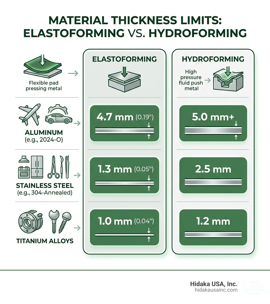
| Material | Max Thickness (Elastoforming) | Max Thickness (Hydroforming) |
|---|---|---|
| Aluminum 2024-O | 4.7 mm (0.19") | 5.0 mm+ |
| Stainless Steel 304 | 1.3 mm (0.05") | 2.5 mm |
| Titanium Alloys | 1.0 mm (0.04") | 1.2 mm |
Core Technologies: Hydroforming, Elastoforming, and Fluid Cells
To choose the right method for your project, you need to understand the "Big Three" of hydraulic prototyping.
- Hydroforming: Uses a liquid medium. It is perfect for complex 3D shapes and ensures 99.996% accuracy.
- Elastoforming (Rubber Pad Pressing): Instead of fluid, this uses a high-density polyurethane elastomer pad. The pad acts as one half of the die, compressing the sheet metal over a rigid tool. It’s incredibly cost-effective because you only have to manufacture one side of the tooling.
- Fluid Cell Technology: A hybrid approach where a large rubber bladder is filled with fluid to apply pressure. While traditional bladders are limited to about 10,000 psi, they offer a great balance for shallow parts like aircraft ribs or automotive brackets.
For those looking for specialized equipment in the Ohio region, Hydraulic Press in Brunswick, OH | Quad Fluid Dynamics Inc. provides insights into the variety of press configurations available for these tasks.
Innovations in Hydraulic Press Prototype Forming
The industry isn't standing still. We are seeing a massive shift toward "bladderless" FluidForming. By removing the rubber bladder, we can achieve pressures up to 60,000 psi. This allows for sharper radii and the use of thinner, lighter materials without the risk of bladder rupture.
We are also seeing a rise in warm forming and hot stamping. By heating aluminum to around 600°F or steel to 1700°F before pressing, we can form high-strength 7000-series aluminum and PHS (Press Hardened Steel) that would otherwise be too brittle. These techniques are essential for modern crash-test-rated automotive components. Companies like Hydraulic and Mechanical and Press & Component Manufacturing are at the forefront of integrating these advanced thermal cycles into the hydraulic process.
Tooling Innovations: 3D Printed Dies and Material Limits
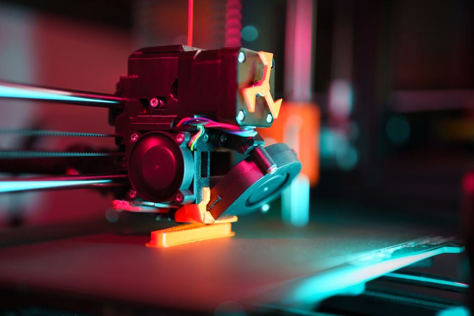
This is where the "magic" happens for rapid prototyping. In the past, you had to wait weeks for a CNC-machined steel die. Today, we use 3D printed tooling made from high-strength polymers like ULTEM 9085.
- Cost Savings: 3D printed dies can reduce tooling costs by as much as 85%.
- Speed: We can go from a CAD file to a physical metal part in 24 to 48 hours.
- Durability: You might think plastic would crush under a hydraulic press, but ULTEM 9085 can withstand over 400 cycles and pressures up to 10,000 psi.
One "hidden advantage" of 3D printed tools is their natural porosity. This allows trapped air to bleed through the layers of the tool during the forming cycle, preventing air pockets that could deform the metal part. We recommend using at least a 65% infill density and 4-5 outer shells to ensure the tool maintains its shape. For high-quality equipment capable of handling these advanced tools, Phoenix Hydraulic Presses | Hydraulic press manufacturer offers robust solutions.
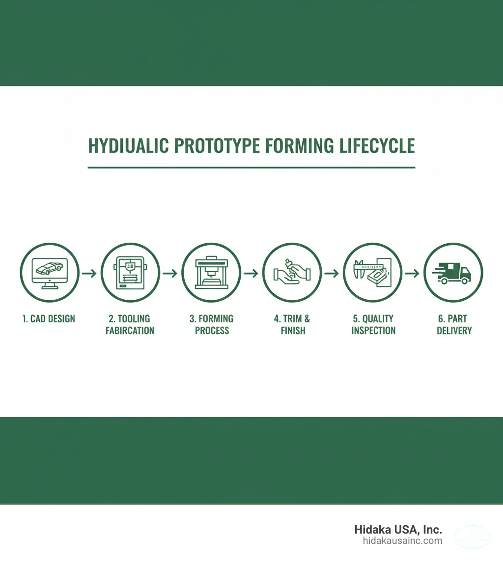
Step-by-Step Guide to the Hydraulic Forming Process
If you're ready to start your first hydraulic press prototype forming project, follow this proven workflow:
- CAD Design: Create your part in 3D. Remember to include generous corner radii to help the material flow.
- Simulation (FEA): Before cutting any metal, run a simulation. This predicts thinning, wrinkling, and the required press tonnage.
- Blank Preparation: Use a laser or waterjet to cut your flat sheet metal blank.
- Tooling Creation: 3D print your mold using ULTEM 9085 or PC (Polycarbonate).
- Lubrication: Apply a water-based lubricant. Avoid petroleum-based products as they can degrade plastic 3D printed tools.
- The Pressing Cycle: Place the blank and tool in the press. Apply pressure gradually, allowing the metal to "settle" into the mold.
- Inspection: Use 3D scanning or CMM to verify the part against the original CAD model.
Optimizing Results in Hydraulic Press Prototype Forming
To get the best finish, we recommend sanding your 3D printed tools with 120 to 320 grit sandpaper. This removes the "stair-stepping" effect of the print layers and results in a smoother metal surface.
Another pro tip: Springback reduction. Because plastic tools have a slight, natural deflection, they actually help counteract the metal's tendency to spring back to its original shape. If you encounter wrinkling, consider using "draw clips" or "forming rings" to hold the edges of the metal blank more securely during the draw.
Frequently Asked Questions about Hydraulic Prototype Forming
What is the maximum material thickness for 3D printed hydraulic tools?
For most 3D printed tools, the limit is approximately 0.090 inches (2.3 mm). Beyond this thickness, the force required to deform the metal often exceeds the compressive strength of the plastic mold. For softer materials like aluminum, you might push this to 1/8 inch, but stainless steel should stay below the 0.090-inch threshold.
How many cycles can a plastic mold withstand in a hydraulic press?
Using a high-grade material like ULTEM 9085, we regularly see 400+ cycles. It is important to note that the tool usually "stabilizes" after the first 10 parts. You might see very slight rounding of sharp corners initially, but after that, the dimensions hold steady for the remainder of the low-volume run.
Why is simulation necessary before starting the hydraulic forming process?
Simulation is your insurance policy. It allows us to calculate the exact press tonnage needed and identifies potential "earing" or "thinning" defects before we waste expensive material. It also speeds up the iteration process—it's much faster to change a digital model than to re-print a tool.
Conclusion
At Hidaka USA, Inc., we believe that prototyping should be a bridge to production, not a barrier. By mastering hydraulic press prototype forming, we help our partners in the automotive and aerospace sectors move from concept to reality in record time. Our 95,000-square-foot facility in Dublin, Ohio, is equipped to handle everything from initial engineering analysis to high-pressure execution.
Whether you are building a prototype for a new electric vehicle or a custom aerospace housing, our ISO 9001 certified processes ensure American-made quality at every step. Ready to take your design from the screen to the shop floor? More info about prototyping services is just a click away. Let's build something great together.