How to Prototype Assemblies: 5 Methods that Guarantee Results

How to Prototype Assemblies for Reliable Product Validation
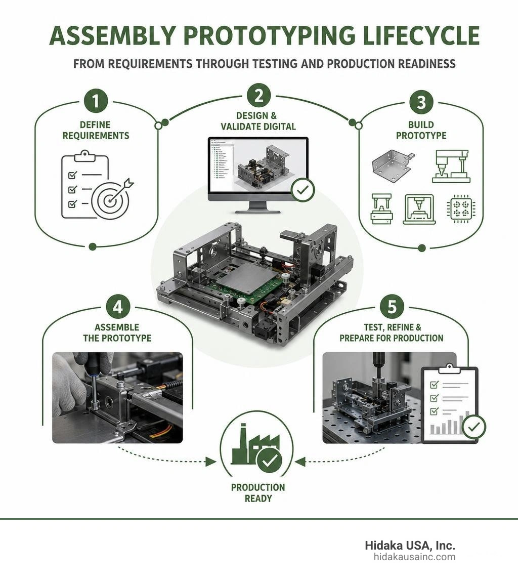
How to prototype assemblies starts with defining what the product must do, then building a physical version that checks fit, function, strength, and ease of assembly before production tooling is approved.
- Define the requirements, operating conditions, critical dimensions, and target materials.
- Build a digital assembly model and check for interference, movement, and tolerance stack-up.
- Choose a prototype method that matches the test goal, such as sheet metal fabrication, CNC machining, stamping, 3D printing, or PCB assembly.
- Assemble the parts using production-relevant fasteners, welds, connectors, or other joining methods.
- Test the prototype, record issues, and refine the design before moving toward mass production.
For automotive and industrial products, an assembly prototype is more than a collection of sample parts. It shows whether panels, brackets, hardware, electronics, and structural components work together under real conditions. Early physical validation can reveal poor fit, difficult assembly steps, weak joints, and sourcing risks before they disrupt a production schedule.
The most useful prototypes are built with the next stage in mind. Using realistic materials, clear build instructions, controlled dimensions, and documented test results helps teams make better decisions during design changes and production planning.
I am Yoshihiro Hidaka, founder of Hidaka USA, Inc. I have worked in automotive prototype and production manufacturing for decades, helping teams understand how to prototype assemblies that can move from early validation to dependable mass production.
Know your how to prototype assemblies terms:
Why Prototype Assemblies are Essential for Product Success
Understanding how to prototype assemblies effectively bridges the gap between digital CAD concepts and real-world physical performance. While single-part prototypes validate isolated geometries, an assembly prototype verifies how multiple components fit, interact, and perform under operational stress. At our facility in Dublin, Ohio, we see how evaluation of full assemblies prevents costly engineering change orders downstream. Leveraging robust Rapid Prototyping Processes early ensures that mating brackets, structural panels, and electrical enclosures integrate without binding or tolerance accumulation issues.
Risk Reduction and Early Defect Identification
Physical assembly validation reveals multi-part interaction defects that 3D software simulations can miss. Placing physical components together exposes thermal expansion constraints, wiring harness pinches, hardware clearance bottlenecks, and hidden interference points. Early physical testing ensures that structural frames, body panels, and internal linkages align under loads before final design freeze.
Cost Savings Before Mass Production
Catching dimensional mismatches during prototyping yields substantial financial savings. Implementing smart Prototyping Cost Reduction Strategies before committing to permanent stamping dies or hard tooling prevents scrap and expensive re-tooling. Catching a single tolerance stack-up error during early physical assembly costs a fraction of fixing a failed production line run.

5 Effective Methods for Prototyping Assemblies
Choosing the right manufacturing process depends on your performance requirements, material needs, and project timelines. Here are five proven methods for building functional prototype assemblies.
1. Sheet Metal Fabrication and Laser Cutting
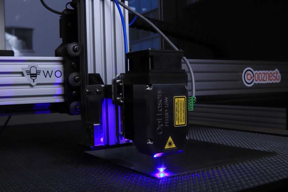
For structural enclosures, transit sub-frames, and automotive bracketry, sheet metal fabrication offers exceptional speed and structural fidelity. Utilizing Laser Cut Prototype Assemblies paired with Precision Sheet Metal Prototyping enables rapid flat pattern blanking followed by precise press brake forming. Spot welding, TIG/MIG welding, and installing self-clinching hardware turn flat sheets into durable, load-bearing metal assemblies ready for rigorous physical testing.
2. Rapid CNC Machining
When prototype components demand high strength, exact alignment, or complex 3D contours, Prototype Machining provides tight tolerances directly from solid metal stock. Machined yokes, housings, and structural mounts maintain material integrity identical to final production parts, ensuring accurate clearance and fit testing.
3. Hydraulic Pressing and Stamping
For complex automotive panels and deep-drawn metal shells, standard bending may not replicate final geometry. Following a dedicated Hydraulic Prototype Forming Guide allows engineers to utilize soft tooling and hydraulic press forces to form complex contours while evaluating stretch limits, springback behavior, and structural integrity.
4. Additive Manufacturing and 3D Printing
3D printing techniques like Selective Laser Sintering (SLS nylon) and Direct Metal Laser Sintering (DMLS, achieving up to 97% density) excel at early concept verification. Additive manufacturing enables complex internal geometries and monoform designs, letting engineering teams check basic spatial clearances without upfront tooling costs.
5. Turnkey Electromechanical and PCB Assembly
Modern mechanical assemblies often integrate electronic control modules and printed circuit boards. Utilizing quick-turn PCBA Prototyping Services allows seamless integration of populated boards into mechanical housings. Modern PCB prototyping can deliver functional boards in as fast as 24 to 48 hours for urgent builds or 5 days for complete turnkey assemblies. Advanced techniques such as 3D X-ray inspection and flying probe testing ensure solder joint integrity and electrical continuity before final mechanical installation.
Step-by-Step Guide: How to Prototype Assemblies from Scratch
Building a complex prototype from the ground up requires structured project management. Reviewing How to Start Prototyping Project guidelines keeps engineering schedules aligned across software modeling, component sourcing, physical joining, and reliability testing.
CAD Modeling and Digital Pre-Prototyping
Before cutting metal or populating circuit boards, refine your digital assembly. Following established SOLIDWORKS xDesign Assembly Modeling Basics allows designers to evaluate component relationships in a single workspace. Managing degrees of freedom, setting up proper constraints, and leveraging software guides like an Introduction to Assembly in Wildfire 3.0 ensures components move correctly.
To streamline modeling, apply Advanced Design Automation Techniques and master time-saving features like Autodesk Inventor Assembly Patterns to place hardware automatically across bolt arrays. For large-scale industrial projects, structuring files according to best practices on How to Handle Large Scale Assembly prevents broken references and reduces CAD processing delays.
Component Sourcing for How to Prototype Assemblies
Managing a Bill of Materials (BOM) for complex assemblies means balancing custom fabricated parts with off-the-shelf hardware. Standardizing structural fasteners, rivets, and connectors reduces lead-time risks. Consolidating fabrication and assembly under a single domestic partner minimizes shipping delays between facilities, ensuring better schedule control.
Physical Joining and Structural Assembly
Transforming individual components into a cohesive assembly requires proper joining techniques:
- Standardized mechanical fasteners (bolts, clinching nuts, rivets) for easy disassembly and inspection.
- Resistance spot welding and AWS-certified arc welding for structural sheet metal joints.
- Precision snap-fits and alignment pins (poka-yoke) to enforce correct part positioning.
Testing Protocols: How to Prototype Assemblies for Reliability
Once built, subject the physical assembly to functional and environmental evaluations. Learn How to Evaluate Prototypes under simulated operational conditions:
- Vibration & Mechanical Shock: Verifies weld durability and fastener torque retention.
- Thermal Cycling: Industrial operating ranges from -40°C to 85°C expose material expansion differences.
- Functional & Electrical Testing: Verifies moving linkages and confirms circuit continuity via flying probe or automated optical inspection (AOI).

Design for Assembly (DFA) and Manufacturability (DFM) Principles
Applying Design for Assembly (DFA) and Design for Manufacturability (DFM) rules early reduces production costs and assembly mistakes.
Minimizing Part Counts and Fasteners
Reducing the overall hardware count speeds up assembly and eliminates potential failure points:
- Part Symmetry: Designing symmetrical housing halves cuts tooling expenses by up to 50% because both sides can share the same setup.
- Self-Mating Clips & Living Hinges: Eliminates external hardware; integrated flexible features can reduce multi-part BOMs significantly, sometimes dropping 13 separate fasteners down to a single molded component.
- Monoform Structures: Utilizing spring geometry directly within sheet metal or molded structures replaces separate shock absorbers and metal springs.
Assembly Manuals and Visual Documentation
Creating clear work instructions prevents shop-floor assembly errors. Modern documentation software allows teams to generate interactive technical manuals directly from 3D models. Following steps on How to Build Your First Assembly Manual in SOLIDWORKS Composer helps authors create exploded views, callout balloons, and 3D PDFs. When design revisions occur, linked documentation updates automatically, keeping assembly instructions accurate.
Overcoming Prototyping Challenges and Scaling to Mass Production
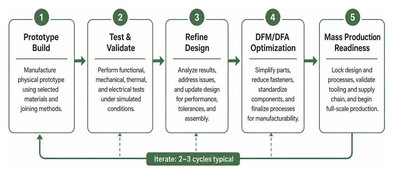
Iterative Prototyping Optimization
In physical hardware prototyping, 2 to 3 iteration cycles are typically ideal for achieving a reliable, well-refined design. Running more than three rounds often indicates deeper issues in initial requirements planning or CAD tolerance stack-up analysis.
Transitioning from Prototype to Mass Production
When moving from initial prototypes to full-scale manufacturing, transition your process parameter settings carefully:
- Production Tooling: Upgrade from soft prototype dies to durable hard stamping tooling.
- Supply Chain Hardening: Establish multi-source component procurement to hedge against component obsolescence.
- Quality Management Systems: Ensure production facilities hold ISO 9001 and industry-specific quality certifications.
- Vendor Alignment: Partnering with an integrated facility that handles both prototyping and high-volume production eliminates technology transfer friction.
To learn more about scaling your project, explore our comprehensive prototyping services and high-volume mass production capabilities.
Frequently Asked Questions
How many iteration cycles are typically required for prototype assemblies?
In professional product development, 2 to 3 iteration cycles are generally ideal. This provides enough physical feedback to resolve tolerance stack-up and fit issues without inflating development timelines.
How do DFM and DFA improve assembly prototyping outcomes?
DFM and DFA streamline component geometry, enforce mistake-proofing (poka-yoke) alignment, and minimize fastener counts. This reduces physical assembly errors, lowers hardware costs, and ensures smooth scaling into mass production.
What is the fastest method to build a functional metal prototype assembly?
Using Rapid Metal Prototyping techniques—such as 2D/3D laser cutting paired with press brake forming and rapid spot welding—allows high-precision structural metal assemblies to be fabricated in days rather than weeks.
Conclusion
Mastering how to prototype assemblies requires balancing digital CAD precision, smart material selection, and rigorous physical testing. By validating fit, structural strength, and assembly workflows early across 2 to 3 iterative cycles, engineering teams prevent costly production delays and ensure superior product quality.
At Hidaka USA, Inc., our 95,000-square-foot facility in Dublin, Ohio offers end-to-end prototyping and mass production services under one roof—including 2D/3D laser cutting, hydraulic pressing, AWS-certified welding, and advanced engineering analysis. Contact our engineering team today to turn your complex assembly concepts into production-ready realities.